Design 4-bit Bcd Up/down Counter From Zero to Ten and Back Again
In the scope of digital logics, a counter is a tool that accumulates the information of how many times a specific process or event is occurring probably like a clock. The generally used type is a sequential digital logic circuit having an input line termed as a clock and has multiple output lines and the values those are on the output lines signify a number in the binary system. Every pulse that acts as input to the clock either increases or decreases the numbers count on the counter. With this operation, counters are usually employed in many applications and these are designed as isolated IC's and even integrated into huge integrated circuits. In consideration of this, this article today explains on BCD counter, its operation, design, and implementations?
What is BCD Counter or Decade Counter?
A BCD (Binary Coded Decimal) counter also termed as decade counter is a series type of digital counter which is designed to count ten digits. It performs the operation of resetting automatically when there is a new clock input signal. As the counter counts ten unique combinations of the applied input, it is termed a decade counter. The values that a BCD counter counts are 0, 1, 2, 3, 4, 5, 6, 7, 8, 9, 10 in binary format, and many others. A four-bit decade counter will operate as a BCD counter by skipping any 6 outputs from the 24 outputs. The most common implementation of this counter is in 74LS90 which is an asynchronous decade counter.
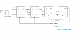
A BCD counter which is designed with JK flip flop is shown below. The outputs from J and K terminals are connected to logic '1'. The clock signal's input in each flip flop is connected to the subsequent flip flop excepting the last flip flop. The NAND gate output is connected parallelly to the CLR signal for all the flip-flops.
Operation
In the decade counter, when the device is at REST mode, the count equals '0' which is 0000 in binary and this is the initial phase of the counter cycle. When a clock signal is connected as an input to the circuit, then the circuit starts to count the binary digits in sequence. The initial clock pulse can be able to count to 9 digits means up to 1001. Then with the arrival of the next clock pulse, the count increases to 10 which is 1010.
Decade Counter with JK Flip Flop
As per the above-shown picture, the ports X1 and X3 will be high. And in the case of high inputs, the output of the NAND gate is at a low position. This output is then connected to the CLR signal as input so that it resets the entire flip-flop stages in the BCD counter. This corresponds that the pulse count from 1001 will reset and tend to initiate from '0000'.
This is the decade counter operation.
Truth Table and State Diagram of Decade Counter
The truth table of the decade counter states about the counting functionality. It signifies the circuit's count in the form of decimals for input pulses. The output of the NAND gate is '0' when the circuit count is 10 which means 1010. This count is then decoded by the NAND gate inputs which are X1 and X3. After the count number is '10', the NAND gate turns from '1' to '0' as it resets all the flip-flops.
Below is the truth table
| Inputs | A | B | C | D |
| 0 | 0 | 0 | 0 | 0 |
| 1 | 1 | 0 | 0 | 0 |
| 2 | 0 | 1 | 0 | 0 |
| 3 | 1 | 1 | 0 | 0 |
| 4 | 0 | 0 | 1 | 0 |
| 5 | 1 | 0 | 1 | 0 |
| 6 | 0 | 1 | 1 | 0 |
| 7 | 1 | 1 | 1 | 0 |
| 8 | 0 | 0 | 0 | 1 |
| 9 | 1 | 0 | 0 | 1 |
| 10 | 0 | 1 | 0 | 1 |
| 0 | Resets to '0' again | 0 | 0 | 0 |
And the diagram that shows the state diagram is as follows:
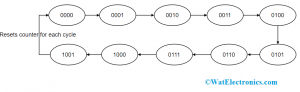
State Diagram of BCD Counter
In the circuit diagram of the decade counter, the operation is explained in four stages where every stage is included with a flip flop. So, the circuits hold the capability of counting 16 states (means 16 bits) where only 10 out of 16 are utilized. The circuit counts from decimal '0' to '9' and after this NAND gate resets the circuits and starts to count again from '0' that is 0000. In this way, many counters can have a series connection in order to count up to our required number.
The number where the BCD circuit can count is termed as "Modulus" also called "Mod". When a counter resets automatically after counting of 'n' bits, it is termed as Mod-n counter where 'n' corresponds to an integer. The Mod counter can count from '0' to '2n – 1'. There exist numerous kinds of counters which can be Mod 4, Mod 8, Mod 5, and Mod 16 counters, and many more.
74LS90 Decade Counter IC Description
In most of the digital kind of electronic circuits and applications, the digital counters are employed through Toggle flip-flops or by using any other kind of flip-flop which can be connected in the way to provide the essential switching operation, or else with the usage of specific counting integrated circuits like the 74LS90. Binary counters are the type of counters which follow a binary sequence and an n-bit counter is designed of "n" number of flip-flops where the count starts from 0 to 2n-1.
The integrated circuit 74LS90 is the most commonly utilized chip in designing a decade counter.
The pin configuration of this IC is explained below:
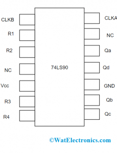
Pin Diagram of 74LS90
It is a 14 pin IC where the supply voltage is 5V and the functional range of ambient temperature is from -55 to 1250C. The power dissipation rate is 45mW and the high-count rate is 42MHz.
| Pin No | Name of the Pin | Pin Description |
| 1 | CLKB | Second clock input |
| 2 | R1 | Reset 1 |
| 3 | R2 | Reset 2 |
| 4 | NC | No connection |
| 5 | Vcc | +ve input supply |
| 6 | R3 | Reset 3 |
| 7 | R4 | Reset 4 |
| 8 | Qc | 3rd pin output |
| 9 | Qb | 2nd pin output |
| 10 | Gnd | Ground |
| 11 | Qd | 4th pin output |
| 12 | Qa | 1st pin output |
| 13 | NC | No connection |
| 14 | CLKA | First clock input |
Explanation of 74LS90
This is a simple counter circuit where it counts from 0 – 9. It is a 4-bit BCD counter, which consists of 4 output ports those are Qa, Qb, Qc, and Qd. When the circuit's count reaches '1010', then the device resets itself to '0'. This happens for every pulse and the other pulse starts at the 9th pin.
The modulus of this IC is configured by altering the R1, R2, R3, and R4 pins where are called RESET pins. For the condition (R1 and R2) is high or (R3 and R4) at the ground, then the counter resets all its output pins which are Qa, Qb, Qc, and Qd to '0'. Whereas for the condition, (R3 and R4) is high or (R1 and R2) at the ground, then the count of output pins Qa. Qb, Qc, and Qd is 1001.
74LS90 Circuit
As it is known that the counting ability of the BCD counter can be increased it can be done by connecting many ICs in the series path. The 7490 IC is internally provided with a divide by 2 and a divide by 5 counters. It can be even employed as divide by 10 counter by 2nd clock input to Qa pin and all the other pins to ground and by providing by pulse input as '1'. The divide by 6 counter is achieved by connecting pulse signal at 1st input and R3 and R4 at ground and Qa with 2nd input pin. In this way, any kind of counter is achieved.
Even the 74LS90 can function as a bi-quinary counter that is utilized to store decimal numbers in the form of 4-bits.
How Decade Counter is used in Frequency Counting?
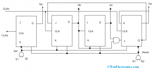
The binary coded decimal counters are even implemented for designing frequency counters. The design is shown below which is done by JK flip flops.
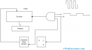
Decade Counter in Frequency Counting
In order to know the frequency value of the unknown counter, the connection is done in the way that unknown frequency is connected to one input and sample pulse signals are connected to other input of AND gate. When these sample pulse signals are at HIGH, the input signal gets transferred to the counter whereas when the pulse signals are at LOW, it is not permitted for low-level sample input pulse signal.
The frequency can be known by dividing the total count's number by the sample time period. The other input for AND gate is provided by JK flip flop in order to hold on to the generated counter result. When the sample pulse signal and JK flip flop input are at HIGH, then the output is reached to counter and then counter resets just by single-shot multivibrator for every +ve terminal of JK by transmitting pulse to it.
Applications of BCD Counter
The crucial benefits and applications of BCD counters are
- Clock production
- Clock division
- United oscillator
- Used in minimal power CMOS circuits
- TTL consistent inputs
- Implemented in frequency counting circuits
On the whole, this is the BCD counter. This article has provided clear and detailed inputs of Decade counter design, truth table, operation, its usage in frequency counting, and applications. Know more on the realistic examples of decade counter and in which domain those are mostly utilized?
Design 4-bit Bcd Up/down Counter From Zero to Ten and Back Again
Source: https://www.watelectronics.com/bcd-counter-design-operation/
0 Response to "Design 4-bit Bcd Up/down Counter From Zero to Ten and Back Again"
Postar um comentário